Skip to content
Render tools
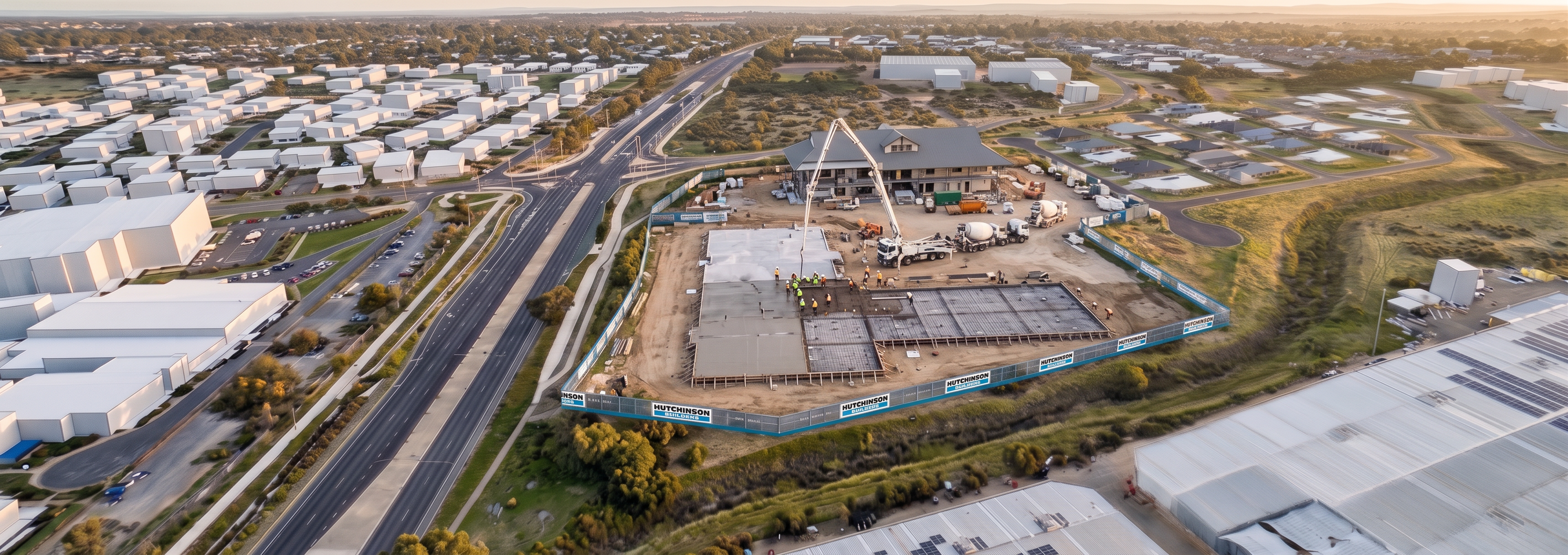
Using the supplied Demolition Render as the master reference image and the supplied Concrete Slab Planning Image as the slab footprint reference, create the next construction sequence showing active concrete slab construction.

This image must appear as a direct progression from the demolition stage.

Critical Camera Requirement

Maintain exactly:

Camera position
Camera angle
Camera height
Perspective
Field of view
Lighting conditions
Shadow direction
Image composition

Do not zoom, rotate, crop or reframe the view.

The output should look like the same drone image captured several weeks later.

Critical Slab Footprint Requirement

The supplied slab planning image shows the exact location and extent of the proposed concrete slab.

This slab footprint is fixed geometry.

Only construct the slab within the footprint shown in the slab planning image.

Do not:

Increase the slab size.
Expand the slab footprint.
Pour concrete outside the nominated building footprint.
Cover the entire site with concrete.
Create additional slab areas.

The slab must occupy exactly the same position shown in the slab planning image.

The footprint location takes priority over all other instructions.

Construction Progress

Demolition is complete.

Bulk earthworks are complete.

The project is now in the active slab construction phase.

The slab should appear approximately:

60-70% complete.
Some areas fully poured and cured.
Some areas being actively poured.
Some areas showing reinforcement and formwork ready for concrete placement.

The viewer should clearly understand how construction is progressing across the footprint.

Concrete Pour Activities

Within the slab footprint only, show:

Concrete pump truck.
Concrete agitator trucks.
Concrete pump boom extended over the active pour.
Workers placing and finishing concrete.
Reinforcement mesh visible in unpoured sections.
Edge formwork.
Concrete finishing equipment.
Small construction crews.

Construction activity should be focused entirely around the slab footprint.

Site Preservation

Retain exactly:

Hutchinson Builders fencing.
Site access.
Site roads.
Existing surrounding development.
Residential housing.
Industrial buildings.
Drainage corridor.
Existing vegetation outside construction areas.

No other changes are required.

Visual Quality

Maintain:

Sharp geometry.
Crisp edges.
Realistic machinery.
Accurate shadows.
High-resolution rendering.
Photorealistic materials.

Avoid:

Distorted buildings.
Distorted roads.
Blurry vegetation.
Artistic interpretation.
Expanded slab areas.
Most Important Instruction

Use the slab planning image as the authority for slab location and size. The concrete slab must be constructed only within the footprint shown in that image. Maintain the exact camera position and surrounding context from the demolition render. Do not extend the slab beyond the nominated building footprint.

Success Criteria

The final image should look like the same Hutchinson Builders site viewed from the identical aerial position, with demolition complete and active concrete pouring underway only within the planned building footprint shown in the original slab sequencing image.

Create renders like this

Turn any photo, sketch, or floor plan into a photoreal render in seconds.