- Prompt
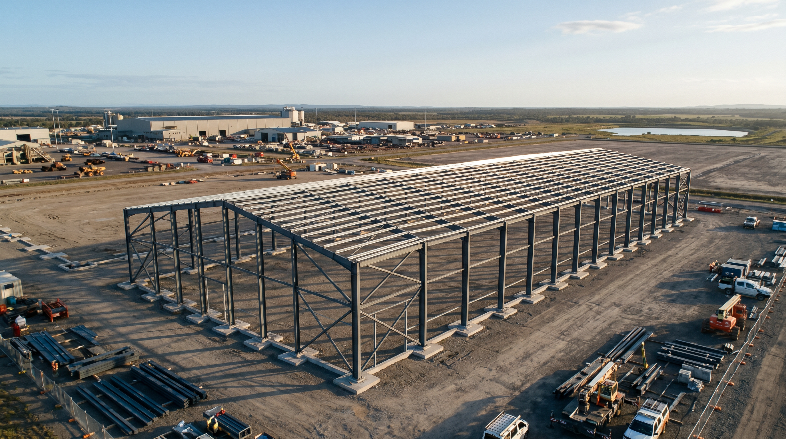
- Create a 3D visualisation of the structural steel frame for this building, using the uploaded S5.01 plan as the primary reference. The S5.01 plan shows all four side elevations of the steel frame—use these elevations to accurately model the height, proportions, and arrangement of all structural steel members. **Instructions:** - Use the S5.01 plan as the main source for geometry, heights, and framing layout. - Combine the information from all four elevations to construct a full 3D steel frame, matching the proportions and member positions shown. - Model all visible structural steel elements: columns, beams, rafters, and any bracing or secondary steel shown in the elevations. - Maintain correct grid spacing, heights, and roof slopes as indicated by the elevations. - Do NOT add architectural finishes, walls, glazing, or cladding—show only the steel frame. - Keep the model clean and uncluttered, focusing on the steel structure itself. **Reference Images:** - Use any additional reference images only for steel material appearance and construction-stage realism, NOT for geometry or layout. **Output:** - Render a 3D perspective or aerial view that clearly shows the full steel frame, including all sides and the roof structure. - Ensure the frame matches the S5.01 elevations in height, span, and member arrangement. **Final check:** - The 3D model must be based on the S5.01 plan, not on any reference photos. - All framing, grid, and layout must match the elevations exactly.
- Created
- June 13, 2026