Skip to content
Render tools
NETBALL COURT FOUNDATIONS

The red outlined court rectangles indicate the exact future netball court locations.

Use these court outlines only as a location reference.

Remove the red outline graphics.

Do not replace the courts with completed gravel platforms.

Do not replace the courts with finished subgrade areas.

Each court area should appear under active foundation construction.

Show:

- Excavated court footprints.
- Foundation preparation works.
- Court edge strip footings.
- Root barrier installation.
- Slotted trench drain installation.
- Open foundation trenches.
- Concrete edge beams.
- Survey pegs and set-out markings.
- Excavators undertaking trenching.
- Civil crews installing drainage.
- Foundation works occurring across multiple courts simultaneously.
- Some court areas further advanced than others.
- Stabilised subgrade installed only in selected sections.

The court areas should remain predominantly construction earth.

The majority of court footprints should still be exposed natural construction material.

Only limited areas should show compacted gravel or subgrade.

The image should clearly represent the transition between civil works and pavement construction.

The courts must not appear complete.

The courts must not appear ready for surfacing.

The courts should appear approximately 30–40% complete.

NO completed court platforms.

NO finished gravel courts.

NO full court subgrade.

NO asphalt.

NO acrylic surfacing.

NO coloured surfacing.

NO line marking.

NO goal posts.

NO chainwire fencing.

NO sports lighting.

NO completed pavement layers.

NO uniform grey court areas.

NO completed netball infrastructure.

The grey shaded carpark footprint should appear approximately 60–70% complete.

Show gravel placement, crushed rock spreading, compaction and pavement preparation.

Do not show asphalt.

Do not show line marking.

Do not show completed parking bays.

The red court outlines are geometry references only and must be replaced with active court foundation construction.

CAMERA REQUIREMENTS

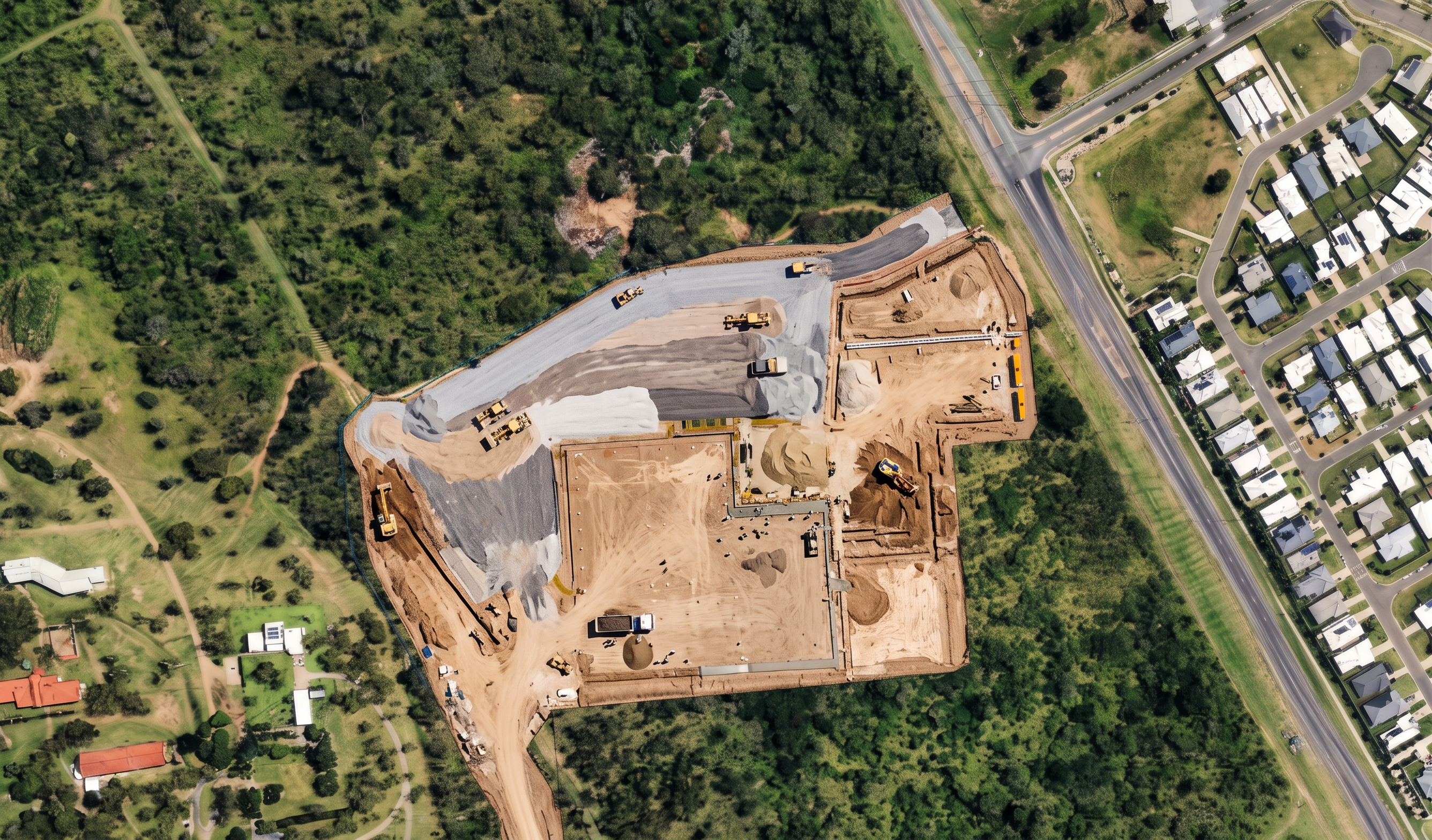
Use a true bird's-eye aerial perspective.

Camera positioned directly above the site.

Near vertical drone view.

Maximum 10–15 degree viewing angle.

Do not use an oblique aerial perspective.

Do not use a cinematic aerial perspective.

Do not use a low drone angle.

The image should look like a construction progress aerial photograph taken directly from above.

The entire site footprint must be visible.

The court layout and carpark areas must be clearly distinguishable.

Maintain the exact footprint geometry shown on the overlay drawing.

Geometry accuracy is more important than visual realism.

Create renders like this

Turn any photo, sketch, or floor plan into a photoreal render in seconds.