- Prompt
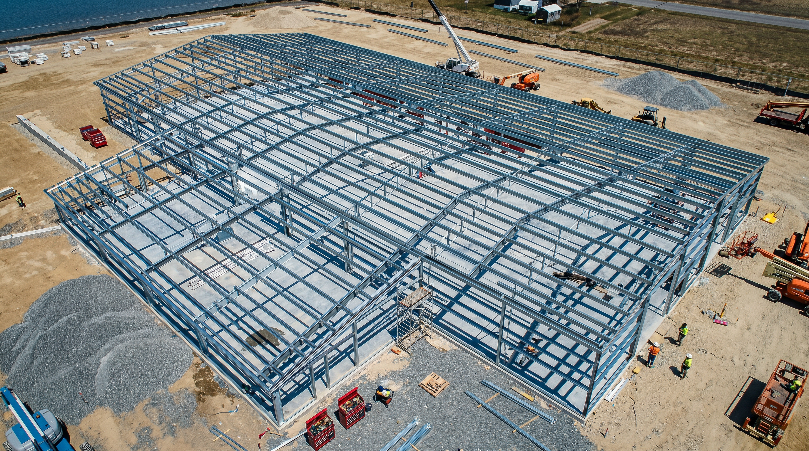
- Create a 3D model and render of the structural steel framing for this project, using ONLY the provided architectural and structural drawings for geometry, layout, and proportions. **MANDATORY INSTRUCTIONS:** - The main image (uploaded plan or drawing) contains the exact geometry and layout. The 3D model MUST match this drawing precisely. - The reference images are for visual style, steel finish, and realism ONLY. DO NOT use them for geometry, layout, or proportions. - DO NOT copy, trace, or base the building shape, grid, or framing arrangement on the reference photo(s). - All framing, gridlines, spacing, and roof pitches must be taken directly from the drawings. **MODELLING REQUIREMENTS:** - Model all structural steel elements shown in the main drawing: - Columns, beams, rafters, trusses, purlins, and secondary steel - Follow all gridlines, spacings, and setouts as shown in the plan - Maintain all roof slopes and heights as indicated - Do NOT add walls, cladding, glazing, or architectural finishes - Do NOT simplify, omit, or guess any framing members **REFERENCE IMAGE USE:** - Use the reference photo(s) ONLY for: - Steel material appearance (galvanised/painted) - Member thickness and edge sharpness - Construction-stage realism - DO NOT use the reference photo for building shape, size, or framing layout **OUTPUT:** - Render a 3D perspective or aerial view that clearly shows the steel framing system - The model must match the uploaded drawing exactly in plan, grid, and proportions - The steel frame should look realistic and construction-stage, but the geometry must come from the drawing, not the photo **FINAL CHECK:** - The 3D model must be based on the drawing, not the reference photo - All framing, grid, and layout must match the plan exactly - The reference photo is for style only, not for geometry
- Created
- June 13, 2026