- Prompt
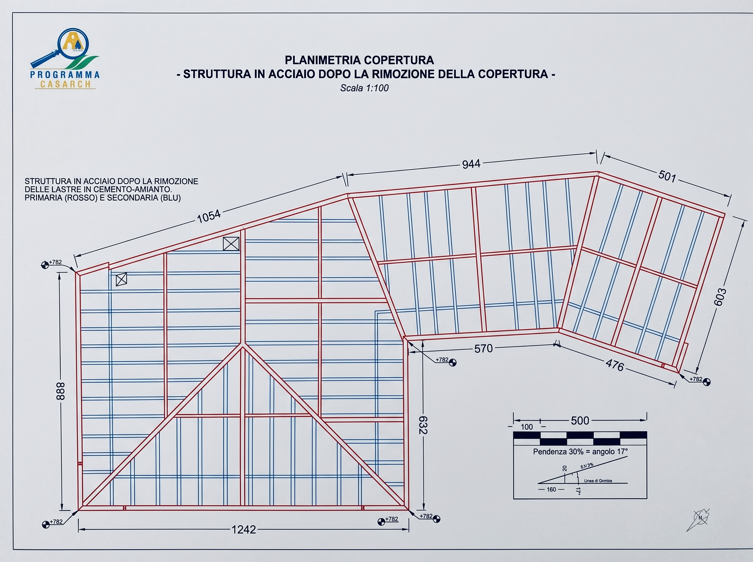
- TECHNICAL ROOF PLAN — STEEL STRUCTURE AFTER ROOFING REMOVAL
Use the uploaded image as the fixed geometric reference. Produce a technical orthographic top view of the existing roof after removal of the corrugated asbestos-cement roofing sheets.
1. ABSOLUTE GEOMETRY PRESERVATION
Preserve the original drawing without redesigning or reconstructing its geometry. Do not crop, rotate, stretch, simplify, regularize or modify any part of the plan.
Keep the entire original roof perimeter, all roof planes, ridges, hips, valleys, eaves, intersections, changes of direction, openings, reference markers, dimension lines and annotations.
The complete right-hand roof extension is mandatory. Preserve its original irregular outline and the dimensions 476, 603 and 501, as well as the dimension 570 and every other dimension shown in the source drawing.
Do not invent, delete, move or alter any roof section or dimensional annotation.
2. REMOVE ONLY THE EXISTING ROOFING
Remove the visual representation of the corrugated asbestos-cement sheets. Reveal the hypothetical supporting metal structure underneath, without changing the original roof outline or the boundaries of the individual roof planes.
3. PRIMARY STRUCTURE — GROSSA ORDITURA
Represent the primary structure using solid-web steel IPE beams. Arrange the beams as a plausible preliminary structural scheme, following the existing roof geometry, principal support lines and intersections between roof planes.
Use red to distinguish the primary beams.
4. SECONDARY STRUCTURE — PICCOLA ORDITURA
Represent the secondary structure using cold-formed C-section steel purlins, supported by the primary beams.
Orient the purlins consistently with the geometry of each individual roof plane and the relevant eaves and ridge directions. Stop, connect or change direction coherently at roof-plane boundaries. Never draw purlins indiscriminately across intersecting roof planes.
Use blue to distinguish the secondary purlins. Adopt an indicative spacing of 80–120 cm, subject to structural verification.
5. TECHNICAL GRAPHIC STYLE
Maintain a strict orthographic plan view and a clean technical drawing style. Preserve the original black dimension lines, annotations, reference markers, drawing proportions and sheet layout.
Do not create a perspective view, a 3D architectural redesign, a new roof shape or decorative elements.
FINAL PRIORITY
The original plan geometry must take precedence over rendering quality. Do not reinterpret the source drawing to improve its appearance. The only intended visual change is the removal of the roofing sheets and the addition of the hypothetical primary and secondary metal framing.
If the original geometry cannot be preserved, do not invent a replacement geometry.
- Created
- October 15, 2026