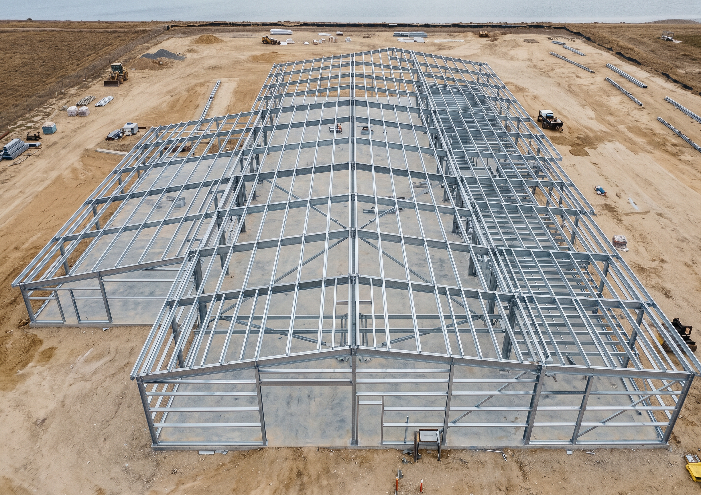
- Prompt
- Create a highly accurate 3D model and rendered image of the structural steel framing only, based strictly on the provided drawings. PRIMARY INSTRUCTION: - The first (main) image contains the primary geometry and MUST be followed exactly. - All other reference images are secondary and provide support only. - Do not interpret, simplify, or redesign anything from the drawings. DRAWING PRIORITY: 1. Main image (STRUCTURAL ROOF FRAMING PLAN) – controls overall building geometry and steel layout 2. Structural framing plan (floor framing) – controls internal beams and columns 3. Grid and setout plan – controls spacing, proportions, and alignment 4. Reference image – for visual style only (not geometry) MODELLING REQUIREMENTS: - Model all structural steel elements including: - Columns (SHS, RHS, CHS as shown) - Beams and bearers (UB, PFC, RHS, etc.) - Roof structure (rafters, trusses, purlins) - Secondary steel framing members where indicated - Follow all gridlines exactly (A–E, 1–5 layout) - Maintain exact spacing and centres (e.g. 4200mm, 3000mm etc.) - Align all elements to centreline of grids unless noted otherwise - Maintain all roof pitches exactly as shown (e.g. 6.5°, 13°) - Accurately model the building footprint including courtyard areas STRICT RULES: - DO NOT add walls, cladding, glazing, ceilings, or architectural finishes - DO NOT change spacing, simplify framing, or adjust layout for visual reasons - DO NOT guess missing elements — omit anything not clearly defined - DO NOT copy geometry from the reference photo REFERENCE IMAGE USE: - Use the steel framing photo ONLY for: - Steel finish (galvanised or painted appearance) - Realistic member thickness and sharpness - Construction-stage appearance - Do not use it to influence layout or geometry LEVEL OF DETAIL: - Maintain correct structural hierarchy (primary beams, secondary members, purlins) - Clean, accurate connections (no need for bolt-level detail unless clearly shown) - Keep the structure readable and logically arranged per drawings OUTPUT REQUIREMENTS: - Generate a 3D perspective render (isometric or aerial view) - Match construction-stage look (bare steel frame on slab) - Neutral lighting and clean background or light site context - Ensure framing system is clearly visible and legible FINAL CHECK: - All steel members must align exactly with the grid and structural drawings - All spacing and geometry must match the main image - No additional or missing framing elements
- Created
- June 13, 2026