- Prompt
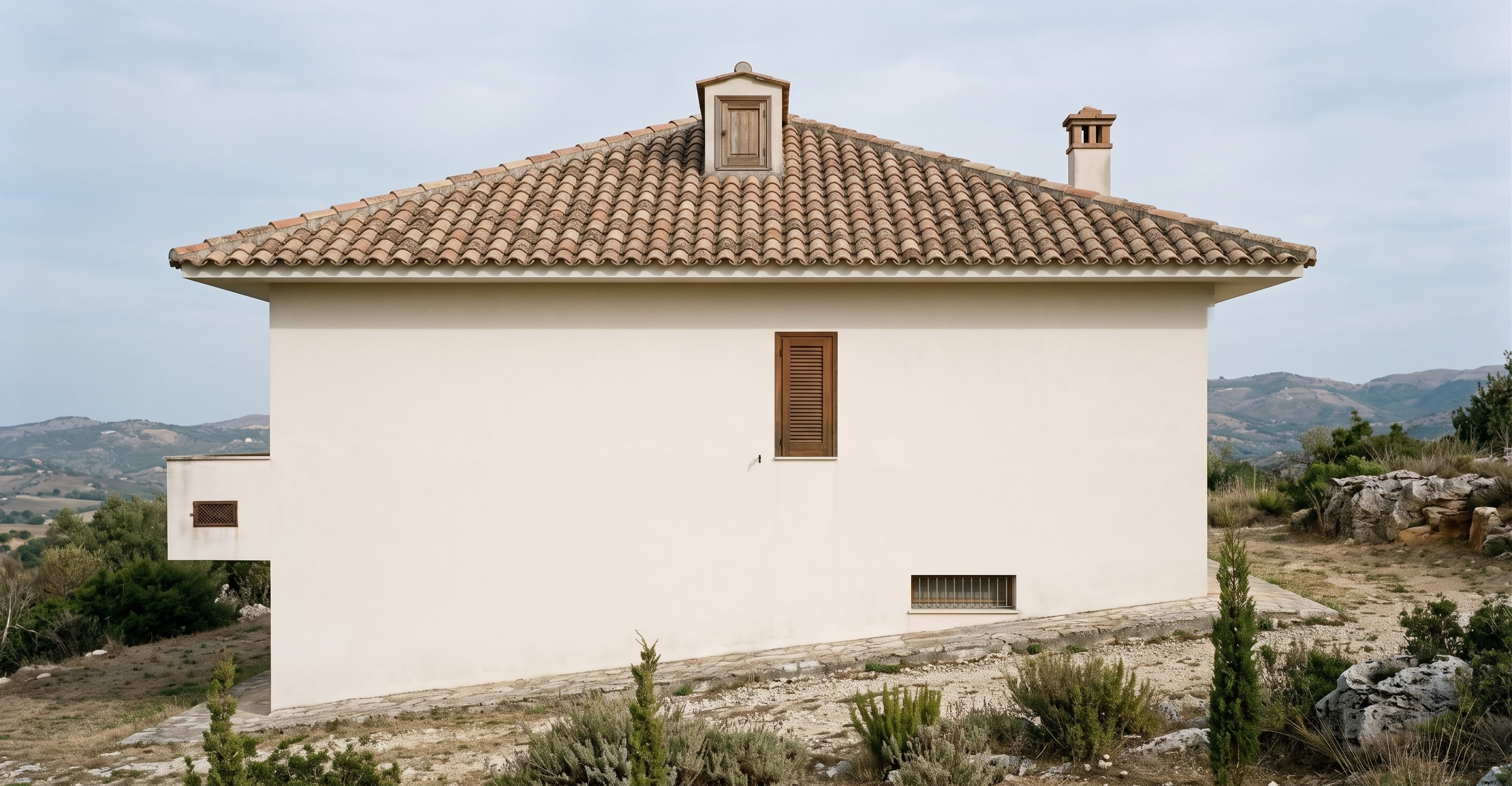
- Create a high-end photorealistic architectural rendering of the SOUTH ELEVATION of the building, using the uploaded technical elevation drawing as the ABSOLUTE and PRIMARY geometric reference.
The uploaded drawing is the exact architectural elevation to be transformed into a realistic finished photograph. It is NOT an inspiration or a conceptual sketch.
PRESERVE EXACTLY the geometry, proportions, dimensions, alignments, positions and relative spacing of every architectural element shown in the drawing.
DO NOT redesign, reinterpret, beautify, symmetrize, move, resize, mirror, add or remove any architectural element.
The final image must remain a STRAIGHT-ON ORTHOGRAPHIC SOUTH ELEVATION, viewed directly from the front, with minimal or no perspective distortion.
IMPORTANT DIMENSIONS:
• main building width: 1110 cm;
• left-side projection: exactly 122.5 cm;
• preserve the vertical dimensions represented in the drawing: 344 cm, 184 cm and 398.5 cm.
PRESERVE EXACTLY:
• the complete hipped roof profile and its exact geometry;
• the exact roof ridge and roof slopes;
• the small rectangular roof opening/element located near the roof ridge, exactly as shown in the drawing;
• the ONE chimney located on the RIGHT roof slope, exactly as shown in the drawing;
• do NOT interpret the small central roof element as an additional chimney;
• the exact position, size and proportions of the single small upper-level window/opening with its dark wooden shutter, located centrally on the facade;
• the large, almost completely blank wall surface exactly as represented in the drawing;
• the exact left-side projecting portion of the building;
• the small rectangular opening/grille in the left projecting portion;
• the small rectangular ventilation grille/opening located in the lower portion toward the right;
• the exact lower ground line and its slope;
• the exact building corners and vertical alignments.
EXTREMELY IMPORTANT:
This SOUTH elevation is largely a BLANK WALL.
DO NOT INVENT OR ADD any windows, doors, balconies, shutters, columns, pilasters, railings, decorative elements, external stairs, additional ventilation openings, chimneys, pipes or other architectural features.
In particular, DO NOT add openings to the large blank wall simply to make the facade more attractive or balanced.
The small upper window/opening shown in the drawing must remain the ONLY main window opening on this facade.
Do not create a symmetrical reinterpretation of the elevation.
The technical drawing contains dimensions, dimension lines and technical graphic information. These are ONLY references for geometry and MUST NOT appear in the final architectural photograph.
The final image must contain NO:
dimensions, dimension arrows, dimension numbers, CAD lines, technical lines, drawing labels, annotations, titles or technical symbols.
Transform ONLY the architecture into a realistic finished building.
Materials:
smooth white exterior plaster, traditional terracotta roof tiles, dark natural wooden shutter, realistic masonry, plaster and metal details.
Lighting:
soft natural daylight under a lightly overcast sky, diffuse illumination, realistic soft shadows and neutral natural colors.
Environment:
a realistic Mediterranean/Central-Southern Italian setting with natural ground and restrained vegetation. The landscape must remain secondary and must never obscure, modify or introduce architectural elements.
Architectural photography:
professional high-end architectural photography, physically plausible lighting, realistic materials and textures, natural colors, high detail, photorealistic.
MOST IMPORTANT RULE:
The uploaded SOUTH elevation drawing is the absolute geometric reference. Preserve the architecture EXACTLY as drawn and ONLY convert the technical representation into a realistic photographic appearance.
- Created
- September 15, 2026